

|
Linyi city source long hardware co., LTD
|
Linyi city source long hardware co., LTD [China (Mainland)]
Business Type:Manufacturer
City: Linyi
Province/State: Shandong
Country/Region: China (Mainland)
Follow Us:

|
Michael Wang:
|
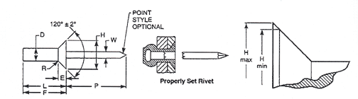
| Rivet Series NO. | Nom Rivet Size | D | H | E | R | W | P | F | L | ||
|---|---|---|---|---|---|---|---|---|---|---|---|
| Body Dia | Style 1 Regular Head | Radius of Fillet | Mandrel Dia | Mandrel Protrusion | Blind Side Protrusion | Rivet Body Length | |||||
| Head Dia | Head Height | All Materials | |||||||||
| Max | Min | Max | Min | .Max | Max | Min | Max | Max | |||
| 4 | 1/8 (.125) | 0.128 | 0.122 | 0.252 | 0.221 | 0.0420 | 0.025 | 0.074 | 1.00 | Equal to "L" Rivet Body Length | See Table 2 |
| 5 | 5/32 (.156) | 0.159 | 0.153 | 0.328 | 0.296 | 0.051 | 0.025 | 0.092 | 1.06 | ||
| 6 | 3/16 (.187) | 0.191 | 0.183 | 0.394 | 0.356 | 0.060 | 0.025 | 0.110 | 1.06 | ||
| 8 | 1/4 (.250) | 0.255 | 0.246 | 0.525 | 0.475 | 0.080 | 0.025 | 0.146 | 1.06 | ||
| See Notes | 3 | 4 | 5 | ||||||||
